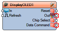
SSD1306/SSD1315/SH1106 OLED Display (SPI)
Jump to navigation
Jump to search
Summary
OLED display module driver supporting SSD1306, SSD1315, and SH1106 controllers over SPI. Provides configuration for display geometry, orientation, contrast, and rendering elements (text, images, graphics, and animations).
Description
The SSD1306/SSD1315/SH1106 OLED Display (SPI) component allows integration of small monochrome OLED screens over SPI. It supports various display controller types, configurable resolution, mirroring, and orientation. Users can render text, images, bitmaps, and graphical primitives, as well as apply scrolling and scene rendering.
Diagram:
Categories
- File:TArduinoDisplayCategory.png Category Display – Screen and display components.
- File:TArduinoSPICategory.png Category SPI – SPI communication devices.
Properties
- SPISpeed – SPI bus speed (default 8000000).
- Background Color – Screen background color (tmcBlack, tmcWhite).
- Contrast – Display contrast adjustment.
- Height – Display height in pixels.
- Mirror – Horizontal/Vertical flip (boolean).
- Orientation – Screen orientation (goUp, goDown, goLeft, goRight).
- Power On – Turns display power on at initialization (boolean).
- Pre-charge Period – Pre-charge timing (Phase1, Phase2).
- Text – Default text properties for rendering.
- Type – Display driver type (odtSSD1306, odtSH1106, odtSSD1315).
- Use Charge Pump – Enables charge pump for power supply (boolean).
- Width – Display width in pixels.
Elements
- Text – Displays text using configurable font and style.
- Render Event – Triggers external rendering events.
- Draw Bitmap – Renders monochrome bitmap images.
- Fill Screen – Fills the screen with a chosen color.
- Scroll – Scrolls text or graphics across the display.
- Graphics – General graphic primitives rendering.
- Draw Scene – Renders predefined graphical scenes.
- Image – Displays stored image data.
- Pixels – Direct control over individual pixels.
- Lines – Draws straight lines between two points.
- Shapes – Draws basic shapes (rectangles, circles, etc.).
Pins
Input Pins
- In (text) – Text input for display rendering.
- Elements – When display elements are added, they create their own input and clock pins automatically.
- Refresh – Clock input to refresh/redraw the display.
Output Pins
- Reset – Digital reset control for the display.
- SPI – SPI communication bus connection.
- Chip Select – Digital chip select line for display addressing.
- Data/Command – Digital control pin to switch between data and command mode.
