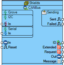
Seeed Studio CANBus Shield V1.2
File:TArduinoSeeedStudioCANBusShieldV1.2.png
Summary
The Seeed Studio CANBus Shield V1.2 provides Controller Area Network (CAN) bus communication capabilities with Grove I2C and serial interfaces for automotive and industrial applications.
Description
This CAN bus shield supports standard CAN 2.0A and 2.0B protocols with configurable bus speeds up to 1Mbps. It features a dedicated chip select pin, configurable clock frequency, and supports various operational modes including listen-only, loopback testing, and one-shot transmission. The shield includes Grove I2C and serial interfaces for easy integration with other components, making it suitable for automotive diagnostics, industrial automation, and robotics applications requiring reliable communication.
Diagram:
Properties
- Bus Speed (kBPS) – CAN bus communication speed in kilobits per second (Default: 500kBPS).
- Chip Select Pin – CAN controller chip select pin number (Default: 9).
- Clock Frequency (MHz) – CAN controller clock frequency in MHz (Default: 16MHz).
- Elements – Configurable CAN bus elements (Default: 0 items).
- Enabled – Enables/disables CAN bus functionality (Default: True).
- Listen Only – Enables listen-only mode (Default: False).
- Loopback – Enables loopback testing mode (Default: False).
- One Shot – Enables one-shot transmission mode (Default: False).
- Sending – Message transmission settings:
- Priority – Message transmission priority (Default: 0).
- Send Timeout (mS) – Transmission timeout in milliseconds (Default: 500ms).
- Sleep – Enables sleep mode (Default: False).
- SPISpeed – SPI communication speed (Default: 8000000).
- Name – Component identifier (Default: Seeed Studio CANBus Shield V1.2).
Pins
Input Pins
- CAN RX (can) – CAN bus receive input.
- Grove I2C In (i2c/grove) – Grove I2C interface input.
- Serial In (serial) – Serial communication input.
- Reset In (digital) – Reset control input.
- Chip Select In (digital) – CAN controller chip select input.
- Power (power) – Shield power supply input.
Output Pins
- CAN TX (can) – CAN bus transmit output.
- Sending Out (digital) – Transmission status output.
- Sent Out (digital) – Message sent confirmation.
- Failed Out (digital) – Transmission failure status.
- Extended Request Out (digital) – Extended frame request output.
- Message Out (digital) – CAN message data output.
Categories
- File:Shield.png – Arduino shield form factor components.
- File:CANBus.png – Controller Area Network components.
- File:Automotive.png – Automotive communication components.
- File:Industrial.png – Industrial communication components.
- File:Grove.png – Grove interface components.
- File:I2C.png – I2C communication components.
- File:Serial.png – Serial communication components.
- File:SPI.png – SPI communication components.
