RFID MFRC522/WS1850S (SPI)
Summary
SPI RFID reader/writer supporting MIFARE and ISO/IEC 14443 Type A protocols with configurable antenna gain and communication parameters.
Description
The MFRC522/WS1850S SPI component is a highly integrated RFID reader IC for 13.56MHz contactless communication. It features configurable antenna gain, multiple modulation schemes, CRC error detection, and support for MIFARE Classic and ISO/IEC 14443 Type A protocols. The component includes advanced signal processing, collision detection, and programmable transmitter/receiver settings. Typical applications include access control systems, inventory management, payment systems, and smart object identification.
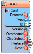
Diagram:
Properties
- SPISpeed – SPI communication speed in Hz (Default: 8000000).
- Antenna – Antenna configuration.
- Enabled – Enables antenna (Default: True).
- Gain (dB) – Antenna gain level (Options: 18, 23, 33, 38, 43, 48) (Default: 33dB).
- Card Operations – Card operation elements:
- Unbrick – Card recovery operation
- Change ID – ID modification operation
- Sector – Sector operations
- CRC – CRC configuration.
- Most Significant Byte First – MSB-first CRC calculation (Default: False).
- Preset – CRC preset value (Options: 0x6363, 0x0000, 0xA671, 0xFFFF) (Default: 0x6363).
- Interrupt – Interrupt configuration.
- Enabled – Enables interrupts (Default: True).
- Inverted – Interrupt polarity inversion (Default: False).
- Open Drain – Open-drain interrupt output (Default: False).
- Name – Component identifier (Default: RFID).
- Parity Check – Parity checking (Default: True).
- Power Down – Power-down mode (Default: False).
- Receiver – Receiver configuration.
- Auto Deactivate – Automatic deactivation (Default: True).
- Conductance Values – Conductance values configuration.
- Negative – Negative signal processing.
- Continuous Wave – Negative continuous wave (Default: 8).
- Modulation – Negative modulation (Default: 8).
- Positive – Positive signal processing.
- Continuous Wave – Positive continuous wave (Default: 32).
- Modulation – Positive modulation (Default: 32).
- CRC – Receiver CRC (Default: False).
- Decode Channel – Decode channel selection.
- Auto Select – Automatic channel selection (Default: True).
- Freeze During Communication – Freeze during comms (Default: True).
- Use In-Phase Channel(I) – Use I-channel (Default: False).
- Enabled – Enables receiver (Default: True).
- External Input – External input configuration.
- Demodulate – Demodulation settings.
- Enabled – Enables demodulation (Default: False).
- Frame Guard Delay (Clock...) – Frame guard delay.
- Ignore Errors – Error ignoring (Default: False).
- Minimal Signal Levels – Minimum signal levels.
- Collision – Collision detection level (Default: 4).
- Decode – Decode level (Default: 8).
- Phase Locked Loop Time – PLL timing.
- Burst – Burst mode (Default: 1).
- Data Receiving – Data receiving mode (Default: 3).
- Power Down – Receiver power down (Default: False).
- Speed (kBd) – Receiver speed (Default: 106kBd).
- Transmitter – Transmitter configuration.
- Additional Response Time – Additional response time (Default: 2).
- CRC – Transmitter CRC (Default: False).
- External Output Pin Mode (MFOL) – External output mode (Options: ThreeState, Low, High, Test, Modulation, TransmitterStream, ReceiverStream) (Default: ThreeState).
- Force Amplitude Shift Keying – Force ASK modulation.
- Inverted – Inverted modulation (Default: True).
- Inverted External Input (MFIN) – Inverted external input (Default: False).
- Miller Modulation Width – Miller modulation width (Default: 38).
- Outputs – Output configuration.
- Enabled – Enables outputs (Default: True).
- External Modulation – External modulation (Default: False).
- Pin1 (TX1) – TX1 pin configuration.
- Enabled – Enables TX1 (Default: True).
- Inverted When Disabled – Invert when disabled (Default: False).
- Inverted When Enabled – Invert when enabled (Default: False).
- Pin2 (TX2) – TX2 pin configuration.
- Enabled – Enables TX2 (Default: True).
- Inverted When Disabled – Invert when disabled (Default: False).
- Inverted When Enabled – Invert when enabled (Default: False).
- Unmodulated – Unmodulated output (Default: False).
- True State – True state output (Default: False).
- Remain Active – Remain active mode (Default: False).
- Speed (kBd) – Transmitter speed (Default: 106kBd).
Pins
Input Pins
- Interface (SPI) – SPI communication interface.
- Chip Select (digital) – SPI chip select signal.
- Reset (digital) – Hardware reset signal.
Output Pins
- Card Detected (digital) – Card detection signal.
- Card Type (text) – Card type identification.
- Card ID (Binary) – Card ID identification.
- Version (Integer) – Card version information.
- Overheated (digital) – Overheating detection.
Categories
- File:SPI.png – SPI communication interface components.
- File:RFID.png – RFID reader/writer components.
- – Wireless communication components.
- File:Security.png – Security and access control components.
- File:Communication.png – Communication protocol components.
