NRF24L01 Wireless
Summary
2.4 GHz wireless transceiver module with configurable data rates, output power, and frequency channels.
Description
The NRF24L01 component is a single-chip 2.4 GHz transceiver with an embedded baseband protocol engine supporting Enhanced ShockBurst™ technology. It features configurable data rates (250 kbps, 1 Mbps, 2 Mbps), adjustable output power levels, and 125 selectable frequency channels. The module includes CRC error detection, automatic packet handling, and multiple power-down modes for low-power applications. Typical applications include wireless sensors, remote controls, gaming peripherals, and home automation systems.
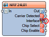
Diagram:
Properties
- CRC Bytes – CRC bytes configuration (Default: 2).
- Data Rate – Wireless data rate (Options: ndr250KBps, ndr1MBps, ndr2MBps) (Default: ndr2MBps).
- Frequency (MHz) – Operating frequency channel (2400–2525 MHz) (Default: 2402 MHz).
- Max Send Queue – Maximum send queue size (Default: 10).
- Name – Component identifier (Default: NRF24L01).
- Power (dBm) – Transmission power level (Default: 0 dBm).
- SPI Speed – SPI communication speed (Default: 4000000 Hz).
Pins
Input Pins
- In (data) – Data input for wireless transmission.
Connections
- Interface SPI – SPI communication interface (MISO, MOSI, SCK bundled).
- Chip Select (digital) – SPI chip select signal (active low).
- Chip Enable (digital) – Chip enable control.
Output Pins
- Out (data) – Data output for received packets.
- Carrier Detected (digital) – Carrier detection signal output.
Categories
- File:SPI.png – SPI communication interface components.
- File:Wireless.png – Wireless communication components.
- – Radio frequency components.
- File:Communication.png – Communication protocol components.
- – 2.4 GHz wireless components.
