Texas Instruments 54HC595/74HC595 Shift Register
Summary
Controls multiple digital outputs using a serial-in, parallel-out shift register.
Description
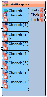
The **54HC595/74HC595 Shift Register** allows expansion of digital outputs using only a few pins from a microcontroller. Each output channel can be set with an initial boolean value, and channels are updated in sequence using serial **data**, **clock**, and **latch** signals.
Diagram:
Categories
- File:TArduinoDigitalCategory.png Category Digital – Digital signal expansion components.
Properties
- Number Channels – Sets the number of output channels (default: 8).
- Channels – Individual output channel settings (Item[0] to Item[7]) with property:
- • Initial Value** – Sets the default boolean state of the channel.
Pins
Pins
- Data – Serial input for channel data.
- Clock – Shifts the serial data into the register.
- Latch – Updates the parallel outputs from the shift register.
- Channels – Digital inputs for each channel (Item[0] to Item[Number Channels-1]).
