Real Time Alarm Clock(RTC) PCF8523
Summary
Provides real-time clock functionality with alarms, timers, and power management using the PCF8523 RTC chip over I²C.
Description
The Real Time Alarm Clock (RTC) PCF8523 component interfaces with the NXP PCF8523 real-time clock via the I²C bus. It supports accurate timekeeping, programmable alarms, timers, power management, and watchdog functionality.
This component is useful for:
Projects requiring time-based events (alarms, scheduled actions)
Low-power applications using battery backup and power switching
Systems that need periodic interrupts or watchdog timers
Embedded systems requiring robust calendar timekeeping with correction offsets
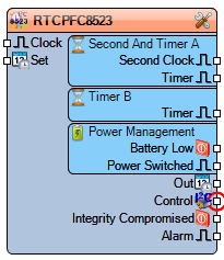
Diagram:
Categories
 Category Generators/Date/Time – Hardware and IC-based time generators.
 Category Date/Time – Timekeeping and scheduling components.
 Category Data Sources/Date/Time – I²C RTC data sources.
Properties
- Address – I²C address of the PCF8523 device.
- Alarm – Alarm configuration:
- Day – Integer day value.
- Hour – Integer hour value.
- Minute – Integer minute value.
- Week Day – Integer weekday value.
- Interrupt Enabled – Boolean; enables or disables alarm interrupt.
- Capacitor12_6 – Boolean; enables internal 12.6 pF oscillator load capacitor.
- Clock Out – Clock output configuration:
- Enabled – Boolean; enable/disable clock output.
- Frequency – Enum (pcf23co32768Hz, pcf23co16384Hz, pcf23co8192Hz, pcf23co4096Hz, pcf23co1024Hz, pcf23co32Hz).
- Elements – Date/Time initialization values: Set Second, Minute, Hour, Day, Week Day, Month, Year.
- Offset – Calibration correction:
- Correction Interrupt Enabled – Boolean.
- Per Minute – Boolean; applies offset once per minute.
- Value – Integer correction value.
- Power Management – Battery and power switching behavior:
- Battery Low Interrupt Enabled – Boolean.
- Power Switch Interrupt Enabled – Boolean.
- Switch Mode – Enum (rtc23psmStandard, rtc23psmDirect, rtc23psmSinglePower).
- Second And Timer A – Timer/clock configuration:
- Clock Frequency – Enum (pcf23tAuto, pcf23t4096Hz, pcf23t64Hz, pcf23t1Hz, pcf23t1_60th_Hz, pcf23t1_3600th_Hz).
- Enabled – Boolean.
- Interrupt Enabled – Boolean.
- Is Watchdog – Boolean; enables watchdog functionality.
- Period – Timer period in seconds.
- Pulse Interrupt Enabled – Boolean.
- Second Interrupt Enabled – Boolean.
- Timer B – Secondary timer configuration:
- Clock Frequency – Enum (pcf23tAuto, pcf23t4096Hz, pcf23t64Hz, pcf23t1Hz, pcf23t1_60th_Hz, pcf23t1_3600th_Hz).
- Enabled – Boolean.
- Interrupt Enabled – Boolean.
- Low Pulse Width – Timer B pulse width in milliseconds (default 46.875 ms).
- Period – Timer period in seconds.
- Pulse Interrupt Enabled – Boolean.
Pins
- Clock – External clock input.
- Set – Date/Time input used to set the RTC.
Outputs:
- Second and Timer A –
- Second Clock (Clock) – Provides a 1-second tick.
- Timer (Clock) – Output from Timer A.
- Timer B (Clock) – Output from Timer B.
- Power Management –
- Battery Low (Boolean) – Indicates low battery condition.
- Power Switched (Clock) – Indicates power switching events.
- Out – Date/Time output from the RTC.
- Control (I²C) – Communication interface with the PCF8523.
- Integrity Compromised (Boolean) – Signals that clock integrity may be lost (e.g., power loss).
- Alarm (Clock) – Alarm interrupt output.
