Adafruit Motor Shield V2: Difference between revisions
Jump to navigation
Jump to search
Created page with "Image:TArduinoAdafruitMotorShieldV2.png == Summary == I2C motor control shield supporting DC motors, servos, and PWM channels with configurable drivers and pulse modulation. == Description == The Adafruit Motor Shield V2 component provides comprehensive motor control capabilities through I2C interface. It supports two driver channels each controlling two DC motors, multiple servo outputs, and 16 PWM channels. The shield features configurable motor parameters includ..." |
No edit summary |
||
| Line 73: | Line 73: | ||
== Pins == | == Pins == | ||
=== Input Pins === | === Input Pins === | ||
*''' | *'''Digital [9] (Servo 2)''' | ||
*'''Digital [10] (Servo 1)''' | |||
*'''Servo In''' | *'''Digital [I2C-SDA] 18 / AnalogIn[4]''' | ||
*'''Motor1 In''' | *'''Digital [I2C-SCL] 19 / AnalogIn[5]''' | ||
*'''Motor2 In''' | |||
*'''PWM0 In''' | *'''Servo → In''' | ||
*''' | *'''Motors / Driver1 / Motor1 → In''' | ||
*'''Motors / Driver2 / Motor2 → In''' | |||
*'''PWM15 In''' | *'''PWM Channels / PWM0 → In''' | ||
*'''PWM Channels / PWM14 → In''' | |||
*'''PWM Channels / PWM15 → In''' | |||
=== Output Pins === | === Output Pins === | ||
*'''Digital | *'''Digital [9] (Servo 2) – Out''' | ||
*'''Digital [10] (Servo 1) – Out''' | |||
*'''Servo Out''' | *'''Digital [I2C-SDA] 18 / AnalogIn[4] – Out''' | ||
*''' | *'''Digital [I2C-SCL] 19 / AnalogIn[5] – Out''' | ||
*''' | |||
== Categories == | == Categories == | ||
Latest revision as of 23:04, 16 September 2025
File:TArduinoAdafruitMotorShieldV2.png
Summary
I2C motor control shield supporting DC motors, servos, and PWM channels with configurable drivers and pulse modulation.
Description
The Adafruit Motor Shield V2 component provides comprehensive motor control capabilities through I2C interface. It supports two driver channels each controlling two DC motors, multiple servo outputs, and 16 PWM channels. The shield features configurable motor parameters including slope control, PWM frequency adjustment, and servo pulse customization. Typical applications include robotics, CNC systems, automated controls, and any project requiring precise motor and servo management.
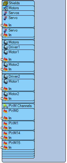
Diagram:
Properties
- Motors – Motor driver configuration.
- Address – I2C device address (Default: 0x60).
- Driver1 – First motor driver.
- Motor1 – Motor 1 settings.
- Enabled – Enables motor (Default: True).
- Initial Value – Initial speed value (Default: 0.5).
- Slope Run – Acceleration slope (Default: 0).
- Slope Stop – Deceleration slope (Default: 0).
- Motor2 – Motor 2 settings.
- Enabled – Enables motor (Default: True).
- Initial Value – Initial speed value (Default: 0.5).
- Slope Run – Acceleration slope (Default: 0).
- Slope Stop – Deceleration slope (Default: 0).
- Motor1 – Motor 1 settings.
- Driver2 – Second motor driver.
- Motor1 – Motor 1 settings.
- Enabled – Enables motor (Default: True).
- Initial Value – Initial speed value (Default: 0.5).
- Slope Run – Acceleration slope (Default: 0).
- Slope Stop – Deceleration slope (Default: 0).
- Motor2 – Motor 2 settings.
- Enabled – Enables motor (Default: True).
- Initial Value – Initial speed value (Default: 0.5).
- Slope Run – Acceleration slope (Default: 0).
- Slope Stop – Deceleration slope (Default: 0).
- Motor1 – Motor 1 settings.
- PWM Channels – Pulse Width Modulation settings.
- PWM0 – PWM channel 0.
- Enabled – Enables channel (Default: True).
- Initial Value – Initial PWM value (Default: 0).
- On Value – Active PWM value (Default: 1).
- PWM11 – PWM channel 11.
- Enabled – Enables channel (Default: True).
- Initial Value – Initial PWM value (Default: 0).
- On Value – Active PWM value (Default: 0).
- PWM14 – PWM channel 14.
- Enabled – Enables channel (Default: True).
- Initial Value – Initial PWM value (Default: 0).
- On Value – Active PWM value (Default: 1).
- PWM15 – PWM channel 15.
- Enabled – Enables channel (Default: True).
- Initial Value – Initial PWM value (Default: 0).
- On Value – Active PWM value (Default: 1).
- PWM Frequency (Hz) – PWM frequency (Default: 1600Hz).
- Sleep – Sleep mode (Default: False).
- PWM0 – PWM channel 0.
- Servo – Servo motor configuration.
- Servo – Servo channel 1.
- Enabled – Enables servo (Default: True).
- Initial Value – Initial position (Default: 0.5).
- Max Pulse – Maximum pulse width (Default: 2400μs).
- Min Pulse – Minimum pulse width (Default: 544μs).
- Reversed – Reverse direction (Default: False).
- Use PWM Library – PWM library usage (Default: False).
- Servo – Servo channel 2.
- Enabled – Enables servo (Default: True).
- Initial Value – Initial position (Default: 0.5).
- Max Pulse – Maximum pulse width (Default: 2400μs).
- Min Pulse – Minimum pulse width (Default: 544μs).
- Reversed – Reverse direction (Default: False).
- Use PWM Library – PWM library usage (Default: False).
- Servo – Servo channel 1.
Pins
Input Pins
- Digital [9] (Servo 2)
- Digital [10] (Servo 1)
- Digital [I2C-SDA] 18 / AnalogIn[4]
- Digital [I2C-SCL] 19 / AnalogIn[5]
- Servo → In
- Motors / Driver1 / Motor1 → In
- Motors / Driver2 / Motor2 → In
- PWM Channels / PWM0 → In
- PWM Channels / PWM14 → In
- PWM Channels / PWM15 → In
Output Pins
- Digital [9] (Servo 2) – Out
- Digital [10] (Servo 1) – Out
- Digital [I2C-SDA] 18 / AnalogIn[4] – Out
- Digital [I2C-SCL] 19 / AnalogIn[5] – Out
Categories
- File:I2C.png – I2C communication interface components.
- File:Motor.png – Motor control components.
- – Servo motor components.
- File:PWM.png – Pulse Width Modulation components.
- – Expansion shield components.
- File:Adafruit.png – Adafruit product components.
- – Robotics and automation components.
