Maxim MAX31865 RTD PT100/PT1000 Resistance Thermometer(SPI): Difference between revisions
Jump to navigation
Jump to search
No edit summary |
No edit summary |
||
| Line 32: | Line 32: | ||
== Pins == | == Pins == | ||
=== Input Pins === | === Input Pins === | ||
*''' | *'''Automatic Test (clock)''' – Starts an automatic self-test cycle. | ||
*''' | *'''Manual Test (digital)''' – Triggers a manual self-test. | ||
*'''Clock''' – System clock input. | |||
=== Output Pins === | === Output Pins === | ||
*''' | *'''Reference Low (digital)''' – Reference resistor low error signal. | ||
*'''Reference High (digital)''' – Reference resistor high error signal. | |||
*''' | *'''Sensor Low (digital)''' – Sensor low signal output. | ||
*'''Sensor Low''' – Sensor low signal output. | *'''Under/Over Voltage (digital)''' – Indicates voltage error detection. | ||
*'''Under/Over Voltage''' – | |||
*''' | ==== Threshold Checking Outputs ==== | ||
*'''Min (digital)''' – Minimum threshold reached. | |||
*'''Max (digital)''' – Maximum threshold reached. | |||
*''' | |||
*''' | ==== Temperature Output ==== | ||
*'''Out (analog)''' – Main analog temperature output. | |||
==== SPI Interface ==== | |||
*'''Control (spi)''' – SPI communication interface. | |||
*'''Chip Select (digital)''' – Chip select input for SPI communication. | |||
== Categories == | == Categories == | ||
Latest revision as of 03:52, 11 September 2025
Summary
The Maxim MAX31865 RTD PT100/PT1000 Resistance Thermometer component reads temperature from RTD sensors using SPI interface. It provides precise temperature measurements with configurable sensor settings and error detection.
Description
The MAX31865 is a precision resistance-to-digital converter designed for platinum resistance temperature detectors (RTDs). It provides high-accuracy temperature measurements from PT100 or PT1000 sensors with automatic error detection including under/over voltage, open circuit, and short circuit conditions. The component supports 2, 3, or 4-wire RTD configurations and offers configurable filtering, measurement timing, and threshold settings for industrial-grade temperature monitoring applications.
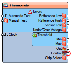
Diagram:
Properties
- Enabled – Enables or disables the component's functionality (Default: True).
- Filter(True=50Hz/False=60Hz) – Noise filter frequency selection (Default: False).
- In Fahrenheit – When enabled, temperature is output in Fahrenheit; otherwise in Celsius (Default: False).
- Name – The user-defined name for the component (Default: Thermometer).
- Sensor – RTD sensor configuration.
- Count Wires – Number of RTD wires (Default: 4).
- Custom – Custom sensor calibration.
- Reference Resistor – Reference resistor value in ohms (Default: 430).
- Zero Degree Resistance – Resistance at 0°C in ohms (Default: 100).
- Measurement Time (mS) – Measurement duration in milliseconds (Default: 65).
- Starting Time (mS) – Startup delay in milliseconds (Default: 10).
- Type – RTD sensor type PT100,PT1000,Custom (Default: PT100).
- Single Shot – Single conversion mode (Default: True).
- SPISpeed – SPI communication speed in Hz (Default: 4000000).
- Threshold – Temperature threshold settings.
- Max (Normalized) – Maximum threshold value (Default: 1).
- Min (Normalized) – Minimum threshold value (Default: 0).
Pins
Input Pins
- Automatic Test (clock) – Starts an automatic self-test cycle.
- Manual Test (digital) – Triggers a manual self-test.
- Clock – System clock input.
Output Pins
- Reference Low (digital) – Reference resistor low error signal.
- Reference High (digital) – Reference resistor high error signal.
- Sensor Low (digital) – Sensor low signal output.
- Under/Over Voltage (digital) – Indicates voltage error detection.
Threshold Checking Outputs
- Min (digital) – Minimum threshold reached.
- Max (digital) – Maximum threshold reached.
Temperature Output
- Out (analog) – Main analog temperature output.
SPI Interface
- Control (spi) – SPI communication interface.
- Chip Select (digital) – Chip select input for SPI communication.
Categories
- File:SPI.png – Components that use SPI communication protocol.
- File:Sensors.png – Temperature sensing components.
- File:Temperature.png – Temperature measurement components.
- File:Precision.png – High-precision measurement components.
- File:Industrial.png – Industrial-grade components.
