Microchip CAN bus - MCP2515 (SPI): Difference between revisions
Jump to navigation
Jump to search
Created page with "Image:TArduinoMCP2515.png == Summary == SPI-connected CAN bus controller supporting standard and extended frames with configurable bus speeds and messaging capabilities. == Description == The MCP2515 component is a stand-alone Controller Area Network (CAN) controller that implements the CAN specification version 2.0B. It supports both standard (11-bit) and extended (29-bit) data frames, operates at bus speeds up to 1 Mbps, and features multiple receive buffers with..." |
(No difference)
|
Latest revision as of 03:45, 15 September 2025
Summary
SPI-connected CAN bus controller supporting standard and extended frames with configurable bus speeds and messaging capabilities.
Description
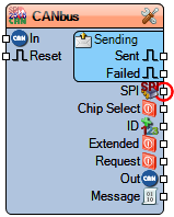
The MCP2515 component is a stand-alone Controller Area Network (CAN) controller that implements the CAN specification version 2.0B. It supports both standard (11-bit) and extended (29-bit) data frames, operates at bus speeds up to 1 Mbps, and features multiple receive buffers with mask filters. The component includes configurable transmission priorities, timeout handling, and loopback modes for testing. Typical applications include automotive systems, industrial control, and vehicle networking.
Diagram:
Properties
- Bus Speed – CAN bus communication speed (Default: 500 kbps).
- Clock Frequency – Controller clock frequency (Default: 16 MHz).
- Elements – Configurable message elements:
- Receive Message – CAN message reception configuration
- Send Message – CAN message transmission configuration
- Request Message – CAN message request configuration
- Enabled – Enables/disables component functionality (Default: True).
- Listen Only – Listen-only mode (receives but does not transmit) (Default: False).
- Loopback – Internal loopback mode for testing (Default: False).
- Name – Component identifier (Default: CANbus).
- One Shot – One-shot transmission mode (Default: False).
- Sending:
- Priority – Transmission priority level (Default: 10).
- Send Timeout – Transmission timeout period (Default: 500 ms).
- Step – Step mode configuration (Default: False).
- SPI Speed – SPI communication speed (Default: 8000000 Hz).
Pins
Input Pins
- CAN In (can) – Logical CAN message input.
- Reset (digital) – Hardware reset signal.
- Chip Select (spi) – SPI chip select signal (active low).
- ID (integer) – Message identifier for outgoing frames.
- Extended (digital) – Selects extended frame format (29-bit).
- Request (digital) – Message request trigger.
Output Pins
- CAN Out (can) – Logical CAN message output.
- Message (can) – Processed CAN message output.
Sending Status Pins
- Sent (digital) – Transmission successful indicator.
- Failed (digital) – Transmission failure indicator.
Categories
- File:SPI.png – SPI communication interface components.
- File:CAN.png – Controller Area Network components.
- File:Communication.png – Communication protocol components.
- File:Interface.png – Bus interface components.
- File:Automotive.png – Automotive communication components.
